


Contents:
Introduction
General Diffraction and Scattering Beamline
Protein Crystallography
Soft X-Ray Spectroscopy and Microscopy
Front End and Standard Beamline Components
Medical Beamline
X-Ray Lithography and Micro-machining
White Beam Diffraction
Introduction
The beamlines and corresponding instrumentation are an integrated part of the facility design that defines the quality of the machine, the efficiency of the usage of photon sources as well as the requirements for civil engineering in addition to accelerator complex. CANDLE can provide more than 50 beamlines that cover the wide spectrum range of emitted photons from VUV to the hard X-ray region. From each dipole of the storage ring two beamlines with source located at 1/3 or 2/3 of the magnet length can be extracted. A scheme of the potential photon beam delivery system from the dipole and ID sources is shown in Fig. 1.
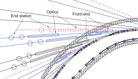
- Fig. 1 Dipole (solid) and ID (dash line) photon beams delivery system.
At the initial stage of machine operation, six beamlines are planed to be functional. The list of the first stage beamlines includes:
- General diffraction & scattering (bending magnet)-BM01A;
- White beam diffraction (bending magnet)-BM01B;
- Protein crystallography (bending magnet)- BM02A;
- LIGA (bending magnet)- BM02B;
- Medical applications (wiggler)-W02;
- Soft X-ray microscopy and spectroscopy (undulator)-U03.
In addition, one beamline from the dipole magnets will be dedicated to diagnostic for the electron beam parameters. The number of the beamlines will be gradually increased according to the demand of the synchrotron radiation users. The machine can be also equipped by the superconducting 7 T wiggler to produce hard X-ray photon beams with the characteristic photon energy of . However, to equip the storage ring at the initial stage, only normal conducting 1.3 T and 1.98 T wigglers are planed. The main photon source parameters from dipoles, wigglers and undulators are listed in Table 1
Table 1 Parameters for the first stage beamlines.
| Source | Magnetic Field (T) | Critical photon energy Ec (keV) | Flux at Ec (photons/sec) |
| Dipole | 1.354 | 8.1 | 1.7 . 1013 |
| Wiggler 1 | 1.3 | 7.8 | 1.9 . 1015 |
| Wiggler 2 | 1.98 | 11.85 | 7.65 . 1014 |
| Undulator 1, n=1,3,5 | 0.3 | 0.85/ 2.6/ 4.3 | – |
| Undulator 2, n=1,3,5 | 0.7 | 1.9/ 5.7/ 9.6 | – |
1 Front End and Standard Beamline Components.
- To maintain the ultra high vacuum of the storage ring in case of emergency or vacuum failure in the beamline;
- To protect people in the experimental station from radiation damage;
- To provide useful photon beam and block useless radiation.
The front end has three important functions:
The important components of the front end are: the diaphragm (fixed mask), the horizontal and vertical slits (movable masks), the fast valve, the vacuum valves, the synchrotron radiation (white beam) shutter, the bremsstrahlung stopper and carbon filter. These components presently designed to be placed inside the storage ring tunnel.
Diaphragm. The diaphragm is a fixed, water-cooled mask. The tapered rectangular opening inside the diaphragm provides angular apertures of 6 mrad in the horizontal direction and 0.2 mrad in the vertical direction.
Fast valve. The fast valve and fast valve sensors represent the vacuum interlock system. The fast valve will be closed in 10 ms when the trigger pressure is reached. The photon shutter, gate valve and stopper will be subsequently closed to protect the vacuum of the storage ring and seal off the front end.
Bremsstrahlung stopper. The stopper consists of a vacuum chamber, a pneumatic manipulator, and a tungsten block of 200 mm length. It absorbs the bremsstrahlung radiation, and should be protected from heating by the synchrotron radiation beam. The characteristic time of stopper closing is 2-3 sec after fast valve snaps into action.
Filter. The filter is a fixed, water-cooled frame with special absorber foils. It will cut off the photon beam in the low energy range. The descriptions of the horizontal and vertical slits and the white beam shutter are given in the next section.
After the shielding wall, the beam line starts, which in general incorporate a number of standard beamline instrumentation techniques. The typical scheme for the photon beam line and its elements is shown in Fig.1.1.
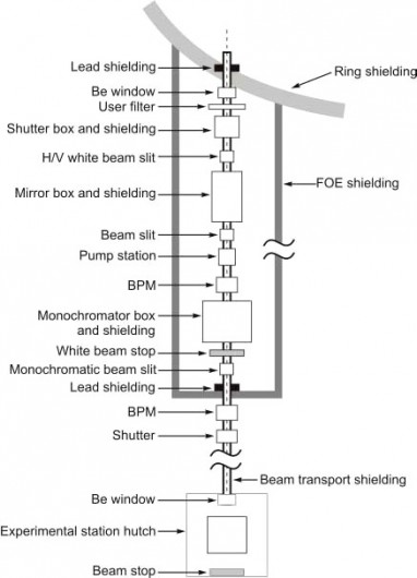
Fig. 1.1 A typical scheme for a beamline.
Filter Assembly. The Filter Assembly is designed to provide the modular beamline filtering system. The assembly is mounted on the user’s beamline on the experimental floor. For the easiness of replacement, the in-vacuum foil filters are mounted on standardized disks. The filters are radiatively cooled to a water-cooled base. The main features of the filter assembly maintaining include:
- Remote selection of X-ray filters;
- White beam compatibility option;
- Multiple filter assemblies with selectable filter combinations;
- Standard filter wheel mounts;
- Motor-driven filter wheels;
- Beamline filters for attenuation and spectral selection.
White Beam Slits for Dipole and ID sources. The white beam slits provide the required working aperture for the white synchrotron radiation from the dipoles and IDs. Standard high load stepping linear actuator modules are used with tapered horizontal and vertical slits, with four independently movable masks in the slit assembly. In addition, the wiggler photon beam slit has typical grazing incidence angle 3°.
Water cooling removes heat from the slit masks. The main features are the following:
- Horizontal and vertical slitting;
- White beam compatibility;
- Four independent precision high load actuators;
- Cooling for structural, vibration, and thermal stability;
- Ultrahigh vacuum compatibility.
The main specifications for the slits are listed below.
| Slit positional resolution: | 10 µm; |
| Slit positional reproducibility: | 25 µm; |
| Vertical aperture: | 0 – 15mm; |
| Horizontal aperture: | 0 – 100mm. |
Monochromatic Beam Slits. The monochromatic beam slits are provided for a precise aperture for the monochromatic synchrotron radiation. Standard light load actuator modules are used with non-tapered horizontal and vertical slits with four independently movable masks in the slit assembly. Convective air cooling removes heat from the slit masks. The main specifications are the following.
| Slit positional resolution: | 1 µm; |
| Slit positional reproducibility: | 5-10µm; |
| Vertical aperture: | 0 – 15 mm; |
| Horizontal aperture: | 0 – 120 mm. |
White Beam Photon Shutters intercept the white synchrotron radiation. Its design is the same as that of the front-end photon shutter.
Safety Shutters Stops intercept bremsstrahlung radiation. The design is the same as that of the front-end safety shutter.
Beamline transport needs to be evacuated to a vacuum level of better than 10-6 Torr. Ion pumps will be used to eliminate the problems with vibrations, noise, heating, and oil penetration. The main specifications are:
| Beamline transport maximum pressure: | 10-6 Torr; |
| Ion pump interface: | to be defined; |
| Flanges: | conflat. |
Kinematic Mount Support Tables and Kinematic Mount Stages. Kinematic mount support tables are provided for a three-point mounting to align the beamline components. The support girders are provided for a rigid base and the isolation from vibration source. The travel of the kinematic mount stages is limited by the bellows location. Tables have five degrees of freedom: vertical translation, horizontal translation transverse to the beam, and 3 rotations. Tables can be operated manually or by using a stepping motor. The main specifications are:
| Minimum support mass: | 1000 kg; |
| x-y-x slides: | 5-10µm; |
| Slide maximum: | +/- 6.35 mm; |
| Slide motion resolution: | 50 µm; |
| Slide motion repeatability: | |
| Slide straightness of trajectory: | |
| horizontal: | 0.1 mrad/25mm; |
| vertical: | 0.2 mrad/25mm. |
FOE and Experimental Station Hutches. Hutches are modular in construction to provide flexibility for users and to accommodate future changes in beamline design. The hutch access door is operated with a push button either inside or outside the hutch. The door will be automatic and operate smoothly. For personal safety, the doors can be manually opened from the inside in case of a power failure. The First Optics Enclosures (FOE) and white beam hutches rest against the storage ring tunnel wall. The monochromatic beam hutches are of stand-alone structures. Hutches are lead lined. The access doors are interlocked for personal safety.
The main specifications are:
| Shielding material: | lead and steel; |
| Shielding thickness: | (see Table 1.1); |
| Shielding construction: | lead core between two steel plates; |
| Access door: | safety interlocked; |
| Hutch height: | 3.5m; |
| Hutch modular panels: | 1m x 3.5m |
Table 1.1 The required shielding for ID and BM experimental stations and transport lines
| Radiation Source | Stainless Steel | Lead | |
| Wiggler | White beam station | 3.2mm | 13mm |
| White beam transport | 3.2mm | 13mm | |
| Monochromatic station | 3.2mm | 13mm | |
| Monochromatic transport | 3.2mm | 3.2mm | |
| Bending Magnet | White beam station | 3.2mm | 1.6mm |
| White beam transport | 1.6mm | 3.2mm | |
| Monochromatic station | 3.2mm | —- | |
| Monochromatic transport | 6.4mm | —- |
Shielded Monochromatic Transport and Pump Station. The shielded monochromatic beam transport provides a standard module for beam delivery on the experimental floor. The lead shielding is encased between two stainless steel pipes (see Table 1.1). The standard section contains a pair of 2 m shielded spool pieces and a 1 m long pump station. The standard pump station includes a gate valve, ion pump, and bellows. The main specifications are:
| Standard length: | 5 m (two 2 m long tubes plus l m pump station); |
| Pump station length: | 1 m; |
| Ion pump speed: | 100 l/sec. |
Be Windows. Beamline Be windows will be designed with vertical apertures approximately consistent with the window’s structural strength. The mount will be designed with a small negative rake to prevent reflections from the mounting fixture. The specifications are:
| Material: | Be; |
| Window thickness: | 250 µm; |
| Vertical aperture: | 20 mm; |
| Horizontal aperture: | (to be specified for maximum aperture consistent with standard flange diameter). |
Monochromatic Beam Position Monitors will be supported on the same type of stand as the front-end BPMs with the resolutions of 0.5 µm within the minimum scanning range of 5 mm.
2 General Diffraction and Scattering Beamline-BM01A
The general diffraction & scattering beamline will produce a moderate flux of hard (5-30keV) focused or unfocused tunable monochromatic X-rays and will sequentially serve two experimental stations:
Experimental Hutch 1 (EH-1) for roentgenography routine or time resolved, low or high temperature structural studies of polycrystalline materials, for reflectivity investigations of thin films and multi-layers, for EXAFS spectrometry;
Experimental Hutch 2 (EH-2) for single crystal structure determination in chemistry and material science, for charge density studies and anomalous dispersion experiments.
The bending magnet source of the BM01A beamline will produce a continuous spectrum of photons with the critical energy of Ec=8.1 keV . The general layout of the beamline is shown in Fig. 2.1. Be window separates the machine and beamline vacuum. In addition, the window cuts the energy spectrum of the photons below 5 keV. The working region for the photon energy 5-30 keV with sufficient flux (~1013 ph/sec, ΔE/E=2.10-4) is then formed by the X-ray optics. Vertical collimation and focusing are provided by two cylindrical mirrors, which also serve to eliminate higher order harmonics . The monochromatization will be performed by a fixed- exit, double-crystal Si (111) monochromator, the second crystal of which is sagitally bent to provide horizontal focusing in case of necessity.
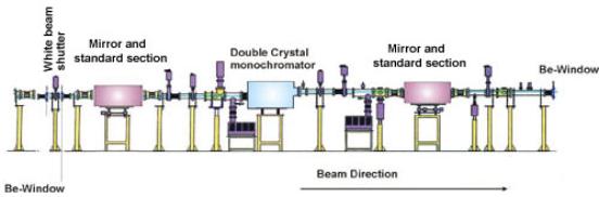
Fig. 2.1 The general layout of the diffraction and scattering beamline.
The beamline X-ray optics is shown in Fig. 2.2. The first mirror (M1) will provide vertical collimation and remove short wavelength higher order harmonics. The mirror consists of a ~1m long Si blank, Rh-coated (K-edge: 23 keV), which can be tilted up to 5 mrad and bent (5<R<30 km) as required for the desired photon energy. The surface of the mirror is polished to a rms roughness less than 0.5 nm and to a rms residual slope error less than 2.5 mrad. The mirror will be cooled (maximum absorbed heat load = 0.35 kW) by water.
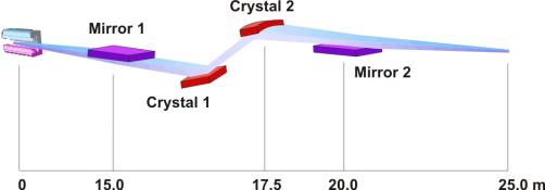
Fig. 2.2 The X-ray optics of the beamline.
The double crystal monochromator (DCM) consists of two Si 111 crystals which are precisely positioned and oriented in the X-ray beam. Two successive Bragg reflections, with an inherent energy resolution of 0.014 %, direct the photons of the desired energy parallel to the incoming beam direction, but offset upward (out of the direct bremsstrahlung beam) by 15 mm. Changes in photon energy require changes in the mirror angle and hence in the height of the DCM. The large heat load absorbed by the first DCM crystal is cooled with liquid nitrogen. The second crystal provides sagittal focusing; it is a ribbed crystal, cylindrically bent to a variable curvature radius (Rmin=1 m) in a flexure-hinge fixture .The second mirror (M2) is similar to M1. A variable curvature will permit vertical focusing at the experimental station in use. Since this focusing introduces a vertical divergence, which is undesirable, for example, high-resolution powder diffraction, the user may choose to either set the radius curvature to infinity or to remove M2 from the beam altogether (the latter option causes an inclined beam).
The X-ray-optical scheme has been simulated by the help of computing code “SHADOW” at the angles of incidence on the mirrors M1 and M2, φ=0.12o, and reflection of the radiation from the crystal of Si 111(DCM) with energy 10keV. The results of the simulation are given in Fig. 2.3.
Fig.2.3 The results of beamline simulation by SHADOW code. The 10 keV photons spatial distributions (cm x cm) are shown: a) the initial beam; b) the reflected beam by the mirror M1; c) the sagittally focused beam after the second crystal DCM at the end station; d) the focused beam at the end station.
Experimental Stations. The photon beam characteristics at the end station of the beamline are given in Table 2.1.
Table 2.1 Photon Beam Parameters at the End Station
| Energy range, keV | 5-30 |
| Crystal type and diff. indexes | Si 111 |
| Energy resolution (Δ E/E) | 2 • 10-4 |
| Flux (ph/sec) at 350 mA (photon energy 10keV) | 6.1 • 1012 |
| Spot size, focused (H x V, mm) | 0.04 x 0.02 |
| Horizontal angular acceptance (mrad) | 6.0 |
| Radius of curvature M1 (km) | 14.4 |
| Radius of curvature M2 (km) | 4.8 |
| Radius of sagittally focusing crystal (m) | 2.07 |
The experimental stations, as was mentioned above, are located in the EH1 and EH2.
The first experimental station EH1 is adopted for Powder Diffraction station that includes the investigations on:
-
structural studies of polycrystalline materials;
-
roentgenography;
-
reflectivity;
-
EXAFS spectrometry.
Experimental apparatuses provided in Powder Diffraction station are:
-
powder diffractometer (designed from Huber goniometric circles);
-
A Huber 513 Eulerian cradle equipped with an XYZ translation table;
-
horizontal and vertical Soller slits, closed-cycle He-cryostat (8 £320K);
-
furnaces for high temperature (T £1800K) studies in air, vacuum and gas atmospheres;
-
NaI-detector;
-
“Amptek” thermoelectrically cooled “Rover” portable X-ray and φ -ray spectroscopy system;
-
ion chambers.
The second experimental station EH2 is designed for Single Crystal diffraction experiments for studying single crystal structure and anomalous dispersion effects. Experimental apparatus in Single Crystal station are:
-
four-circle “Oxford Diffraction “ kappa goniometer KM4 with Sapphire series CCD detector;
-
nitrogen cryogenic attachment;
-
high temperature attachment (1800K)
3 Medical Beamline
The application of the synchrotron X-ray beams for medical purpose becomes an important part of the synchrotron radiation use and openes an opportunity for the best medical diagnosis and treatment. Actually all the modern synchrotron radiation sources are accompanied by the satellite medical center. The highlights for medical therapy and diagnosis by the use of synchrotron radiation of CANDLE synchrotron light source include:
- Angiography;
- Bronchography;
- Mammography;
- Computed Tomography;
- Diffraction Enhanced Imaging Microangiography;
- Microbeam Radiation Therapy.
To cover this wide area of the medical applications for the radiation therapy and treatment, two beam lines, one from wiggler and one from bend magnet, can be delivered to medical center as an extension of the end stations at the experimental hall of the CANDLE light source. The wiggler beamline specification and technique to be used are presented in this section. The 2 T magnetic field wiggler beamline from CANDLE has a critical photon energy of about 12 keV, the spectrum of which is extended up to 100 keV with sufficient photon flux and covers the photon energy of 33.17 keV – the iodium K-edge energy. The full length of the beamline is about 140 m. The X-ray beam produced by the wiggler magnet passes out of the experimental hall and enters into the satellite laboratory. The parameters of the wiggler source is presented in Table 3.1
Table 3.1 The Beamline Source
| Critical photon energy (keV) | 11.88 keV |
| Magnetic field (T) | 1.98 T |
| Electron beam spot size (μm’ μm) | 314.2 × 20.18 (H × V) |
| Electron beam divergence (μrad x μrad) | 32.4 × 4.16 (H × V) |
| Total power emitted (kW) | 29.9 |
| Flux at critical photon energy (ph/s*0.1%bw) | 6.5 · 1015 |
Different experiments can be performed at the end station located in the main experimental hall of the CANDLE and the end stations. Medical wiggler beamline will produce a high flux of hard X-rays and sequentially serve three experimental stations for medical applications:
-
Experimental Hutch 1 (EH1) – microbeam radiation therapy;
-
Experimental Hutch 2 (EH2) – computed tomography;
-
Experimental Hutch 3 (EH3) – coronary angiography / bronchography.
Microbeam radiation therapy (MRT) is aimed at clinical applications. The theory and rationale of pre-clinical experiments of MRT are based on dose-volume relationships that shape tissue complications after ionizing irradiation. In general, the smaller the irradiated macroscopic tissue volumes, the higher the threshold of absorbed doses to damage normal tissues. Present-day clinical applications of this principle include stereotaxic radiosurgery and conformal radiotherapy, using photon beams collimated in millimeters.
Computed tomography (CT) is widely used in clinical practice and produces images of high diagnostic quality. Nevertheless, there are some difficulties related to the use of conventional sources for CT. In particular, beam hardening, where the higher energy photons have higher probability of traversing a large tissue thickness than the lower energy photons do, is a troublesome problem in image reconstruction. Synchrotron radiation has some obvious advantages that is the monochromatic beams will not beam harden whilst the tunability of the beam permits K edge subtraction imaging.
Coronary angiography / bronchography. The high brilliance and tunability of CANDLE X-ray beams can dramatically improve the speed, clarity and safety of diagnostic tools, such as coronary angiography and computed axial tomogarphy scans.
The coronary angiography is an X-ray procedure in which coronary vessels are made visible through the injection of iodine as a contrast medium. Two X-ray beams, one tuned to an energy readily absorbed by the iodine and one at the slightly lower energy, are used to record two images simultaneously. When the computer subtracts one image from the other, the contrast of view of the arteries is enhanced 150 000 times over that of bone or flesh. This extreme sensitivity allows the use of much lower iodine concentrations and lower X-ray doses, compared with conventional angiography. With such low iodine level, the contrast agent can be safely introduced through an arm vein. And by using the high brilliance of CANDLE X-ray beams, an image can be formed in milliseconds, fast enough to make “snap shots” and “movies” of the living, beating heart and nearby arteries. Monochromatic X-rays of sufficient intensity to visualize coronary arteries of 1 mm in diameter with an extremely low iodine mass density of 1 mg/cm2 are only provided by synchrotron radiation.
The same technique can be applied for the imaging of lungs and respiratory passages- bronchography. The patient inhales a gas mixture of xenon (80%) and oxygen (20%). The inspired volume is limited to the anatomic dead space, which includes the small bronchi but not the alveoli, and therefore virtually no xenon is absorbed. Moreover, this protocol limits overlap problems caused by xenon in the alveoli or in vascular structures. The patient then holds his/her breath for several seconds whilst dual energy imaging is performed in a manner very similar to that used for line scan coronary angiography. The only difference is that the energies are chosen to bracket the Xenon K edge at 34.56 keV. The technique could be particularly valuable in the early diagnosis of lung cancer, which is the leading type of cancers. It is calculated that K edge subtraction imaging using inhaled Xenon as a contrast agent could detect tumors that are significantly smaller than the 1cm limit of conventional techniques.
The monochromator for angiography (bronchography) is based (Fig.3.1) on the use of a cylindrically bent Si-crystal in a vertically focusing Laue geometry. The white beam is diffracted by the thin crystal. A water-cooled beam splitter, located downstream from the crystal, divides the diffracted beam into two beams with energies above and below the iodine K-edge. The parameters of the monochromator are presented in Table 3.2.
Table 3.2 Monochoromator characteristics.
| Optical elements | Si-bent Laue crystal | Fixed-exit monochromator |
| Distance from source | 145 m | 140 m |
| Usage | Angiography | Computed tomography |
| Spectral range | 17-51 keV | 15-80 keV |
| Max beam size at patient | 300×10 mm2 (HxV) (aperture limited) | |
| Expected flux | 1.1 X 10¹⁵ph/s, 0.1% bw, 0.350 A, 33 keV |
Fig. 3.2 presents the results of the computer simulation of dual energy quasi-monochromatic synchrotron radiation beam formation (the energy range 33170 ± 250 eV) after the monochromator that is obtained via the Si (111) Laue diffraction (Fig. 3.2a). The photon beam image at focus location after the beam stopper
(2 mm vertical size) is shown in Fig. 3.2b and finally the photon beam image at the detector is given in Fig. 3.2c.
The monochromator parameters – radius of curvature, thickness, and diffraction asymmetry factor – will be further optimized to obtain a maximal intensity of the diffraction radiation with the minimum size in a vertical direction. Accordingly, the horizontal and vertical apertures of the beam before and after a crystal, distance between the patient and the detector, and distance between two rulers of the detection system will be adjusted.
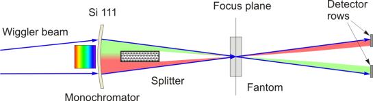
Fig. 3.1 Schematic layout for the angiography/bronchography beamline at CANDLE.
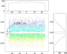
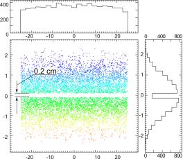
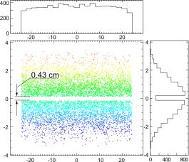
Fig. 3.2 Result of the computer simulation of a quasi-monochromatic SR beam (energy range 33170 250 eV) obtained via the Si (111) Laue diffraction monochromator. Beam image a) at 15cm after monochromator, b) at focus location after the beam stopper, c) in place of detector.
The apparatuses associated with end station for coronary angiography and bronchography (EH3) include:
- In house design and production goniometer and crystal monochromator with bender;
- Special chair for patient;
- Radiation detecting system – high purity germanium detector associated with high dynamic range electronics (864 strips distributed over two rows with detection pitch of 350 micrometers).
4 Protein Crystallography
The beamline is specialized for macromolecular crystallography. It is dedicated to Single wavelength Anomalous Diffraction (SAD) and Multiple-wavelength Anomalous Diffraction (MAD) experiments, as well as any other macromolecular crystallography experiment that requires lots of photons. Three experimental stations sequentially serve for protein crystallography:
- EH1- (MAD1) is suited for MAD
- EH2 – (MAD2) is suited for MAD
- EH3 – (SAD) will deliver photons at a fixed energy of 13.8 keV.
Experimental technique
During a standard protein crystallography experiment the intensities of the diffracted X-ray beams are recorded. Unfortunately, their relative phases, crucial for reconstructing an image of the molecule, are lost and have to be determined indirectly, either by making additional measurements or by exploiting some prior structural knowledge.
Multi-wavelength anomalous dispersion (MAD) is the method of macromolecular phase determination that exploits the tunable energy capability of a synchrotron X-ray source. Using a highly monochromatized X-ray beam the experimenter is able to probe the anomalous scattering from some heavy atoms, incorporated into the target molecule.
The method requires X-ray diffraction measurements at two to four X-ray energies near the atomic absorption edge of the heavy atom, chosen to maximize the real and imaginary components of anomalous scattering. MAD phasing is rapidly becoming the method of choice for determining new crystal structures of small to medium-sized proteins, and MAD has succeeded for a variety of anomalous scatterers including Se, Fe, Cu, Br, Tb, Pt, and Hg. The location of the atoms in this, often simple, anomalous scattering sub-structure can then be used as in solving the complete molecular structure. The use of selenomethionine substitution as a method of readily incorporating anomalous scatterers has allowed the technique to become broadly applicable to a large variety of macromolecular systems. However, for the large unit cells, e.g. viruses, ribosomes and other large assemblies the standard MAD phasing over the energy range of 5-17.5 keV is required. This would be from the iron K edge to the uranium LIII edge ( Fig.4.1).
The advent of cryogenic cooling of protein crystals has reduced the requirement of rapid wavelength tuning. However, it is still important to be able to easily and accurately change between wavelengths without disturbing the sample. In addition to the normal demands on a beamline for protein crystallography of high flux, collimation, and limited divergence, the MAD phasing requires the ability to change between wavelengths and to have an energy resolution Δ E/E of 1-5×10⁻⁴ although structures have been solved with energy resolutions as large as Δ E/E = 10-3 .
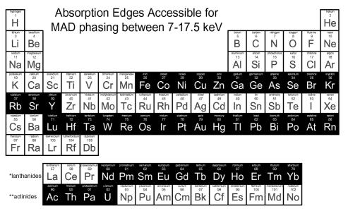
Fig.4.1 Periodic table with accessible edges in black.
Beamline layout and optics
The main requirement for protein crystallography beamline is to have the maximum intensity in the energy range of 5-17.5 keV. However, tunability is only required for certain purposes (e.g. anomalous dispersion). Beam sizes for the sample range between 0.05mm to 0.5mm with 0.2mm being a useful average. The divergence requirements are of the order of 10 mrad. Protein Crystallography beamline source is a bending magnet which consequently produces a continuous spectrum of photons with a critical energy of Ec =8.1 keV.
The general layout of the beamline is shown in Fig. 4.2. The beamline consists of three sub-beamlines MAD1, MAD2 and SAD that are integrated in the front-end. The first two serve experimental stations (EH1 and EH2) for macromolecular crystal structure studies using MAD phasing and the third one serves the experimental station for SAD phasing.
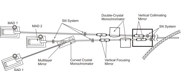
Fig. 4.2 General layout of protein crystallography beamline.
The X-ray optics of the sub-beamlines for MAD1 and MAD2 are identical to the optics of diffraction beamline (Fig. 2.2) and effectively focuses the quasi-monochromatic tunable radiation in the photon energy range of 5-30 keV. The transverse size of the focused beam is 0.4 mm in the horizontal and 0.2 mm in the vertical planes with an intensity of 6.1012 photons/s. At the experimental hutch for SAD, a fixed energy of 13.8 keV for the focused beam is obtained by the following beam manipulations. Part of the beam is reflected by a vertical collimating mirror followed by the DCM and focusing mirror, and is diffracted and focused in horizontal direction by bent Si monochromator to the sample at experimental station for SAD. The vertical focusing is performed by the multi-layer mirror. The expected focal spot of the beam is 0.4 mm horizontal and 0.4 mm vertical. The optic elements for the MAD1 (EH1) and MAD2 (EH2) beamlines include water- cooled Si blank, Rh-coated collimating and focusing bent mirrors. The Double Crystal Monochromator is composed of goniometer, full in-vacuum Si 111 crystal pair monochromator (energy range 5-30 keV) and 2nd crystal bender for sagittal focusing.
The optics element for SAD (EH3) with a fixed photon energy of 13.8 keV include curved Si220 water cooled triangular crystal monochromator, bender for horizontal deflection and focusing, and cylindrical multi-layer (Si/W) for vertical focusing.
Experimental Stations
The experimental stations for MAD1 ( EH1) and MAD2 (EH2) are based on:
-
Single crystal kappa diffractometer (designed from Huber goniometric circles);
-
A Huber 513 Eulerian cradle equipped with an XYZ translation table;
-
Detector – MAR CCD;
-
700 Series “Oxford Cryosystems” cryo-steam cooler;
-
Standard microscope for mounting sample.
The experimental station for SAD (EH3) is based on the same apparatus with CCD replaced by Image Plate MAR345.
Laboratory Facilities
Basic crystal mounting equipment will be available on the station. It will include a device to melt wax in order to seal capillaries, different sizes of dewars for the handling of frozen crystals, 2 stereo microscopes, deionised water, a small fridge to store crystals between 4 deg C and 25deg C. The list of main equipments for life science investigations will include crystal mounting, centrifuges, chromatographs, electrophoresis equipment, UV/Visible recording spectrophotometers, fermentors, autoclave, vacuum concentrators and other common equipment and supply for biochemical laboratory.
5 X-Ray Lithography and Micro-machining
The development of the experimental technique for X-ray imaging, known as LIGA (German acronym for Lithographe, Galvanoformung, und Abformung), made very effective the application of synchrotron radiation for the large integrated circuit fabrication and three dimensional device machining with very high resolution. The resolution comes from the extremely short wavelength of synchrotron radiation, of the order of 0.01-1.0 nm, and the high penetration ability, arising from the transparency of most materials in this region of the spectrum.
The LIGA technique is based on exposing a photoresist material by synchrotron radiation X-rays through properly designed mask and consists of deep-etched X-ray lithography, electroplating and micro-molding. The main elements of the LIGA are the mask that carries the pattern to be transferred, imaging system and the storage medium (photoresist) deposited over the surface of the wafer. The incident X-ray synchrotron radiation produces the shadow of the mask pattern at the photoresist surface. A photoresist, a thin film of photosensitive material, is deposited on top of the wafer prior to exposure by the X-ray source. When the resist is exposed to the radiation, the mask pattern is stamped on the resist thus transferring the mask pattern to the wafer/resist layers.
Consequent using of different masks with various exposing time a complex structures can be produced with few mm height and sub-micron level of lateral resolution.
LIGA technique can be used for production of:
- Microscopic machines known as MicroElerctroMechanical Systems (MEMS);
- Positioning structures and switching components for optical fiber communication;
- Miniature motors, gears, pumps and heat exchangers;
- Micro-optical components;
- Microsurgical tools.
The CANDLE beamline, specialized for Lithography and Microfabrication using LIGA technique, will be based on the dipole synchrotron radiation and will be supported by the experimental Station (EH) located at the distance of 15m from the source point. The LIGA beamline is the most simple compared to beam lines for other applications. No special optics is required for this beamline. The white radiation is formed by 15 mrad horizontal fun to provide 100 mm horizontal beam width at the exposure plane located at 15 m. The input beamline window is provided by 250 µm thick Beryllium plate. The transmitted bandpass spectrum of the radiation covers the energy range of 2.6 – 30 keV with the photon flux at 5 keV at the level of 2.25×10¹⁴ ph/s (Fig. 5.1). The usage of 1.25 mm Be window does not significantly affect the intensity of the radiation over 5 keV photons energy. To filter the white beam, the graphite plate assembly with equivalent thickness of 6-300 φm will be used. The experimental apparatus at experimental hutch will allow the sample vertical scan up to 100 mm with the maximum scanning rate of 50 mm/s.
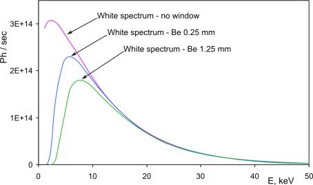
Fig 5.1 Spectral Flux of LIGA Beamline for different Be plate thickness
6 Soft X-Ray Spectroscopy and Microscopy
Using SR soft X-ray wavelength, the investigations on photoluminescence, photoemission, transmission- X-ray absorption near edge spectroscopy (NEXAFS) and specular reflectivity, defect formation, microanalysis of polymers, hydrated, colloidal, environmental, etc, are carried out in molecular crystals, ionic crystals and scintillators. Very high flux and pulsed properties of radiation from insertion devices offer the possibility for the use of such powerful techniques as electron paramagnetic resonance (EPR) and optically detected magnetic resonance (ODMR) for the studies of excited states or defects in solids.
The parameter list of undulator magnet that supposed to support this experimental program is given in Table 6.1. The 35 periods with a period length of 8 cm and minimum gap 7 mm will provide irradiation in soft X-ray range. The undulator source will serve:
-
A soft X-ray spectroscopy – (SXS);
-
A soft X-ray microscopy – cryo scanning transmission microscopy (cryo-STXM);
-
Scanning transmission X-ray microscopy (STXM)
Table 6.1 Undulator parameters
| Undulator 1 | K=5.5 | K=1 |
| Photon energy range (eV) | 50 | 712 |
| Horizontal size (mm) on the distance 15 m | 1.44 | 0.7 |
| Vertical size (mm) on the distance 15 m | 1.32 | 0.38 |
| Horizontal divergence (μrad) | 93.74 | 41.1 |
| Vertical divergence (μrad) | 87.98 | 25.36 |
| Flux calculated on the distance 15 m photon/s/mm2/0.1%BW) | 1.69×10¹⁵ | 9.69×10¹⁴ |
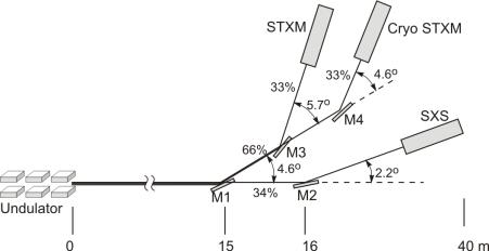
Fig.6.1Soft X-Ray beamline layout and optics
The beamline will produce a high flux soft X-ray (50-1800eV) and will support three experimental stations on: spectroscopy (SXS) (EH1) and two scanning transmission microscopy on cryo-STXM (EH2.1), room temperature STXM (EH2.2) (see Fig. 6.1).The beamline is a compound of the existing beamlines in HASYLAB-DESY, NSLS. Soft X-ray spectroscopy and microscopy beamline is divided into two beams via the mirrors. The first photon beam for SXS covers the energy range of 50 – 1800eV (34%), the second photon beam covers the energy range of 200 -1000eV (66%). The second photon beam line in turn is equally divided into two parts for cryo-STXM and STXM, and each of them is using Freznel zone-plate for focusing the beam into the sample.
Soft X-ray Spectroscopy
The beamline optics are shown in Fig. 6.2. The first optical element of the beamline is water-cooled mirror coating by Ni, Au or SiO2 that reflect the beam at angle of 2.2o over the large photon energy range (from 50 to 1800 eV).
The entrance optics consist of two mirrors – first plane M2 and the second (toroidal) S0 for vertical and horizontal focusing. The reflecting mirror S0 can have two positions with angles 1.2o, 2.7o that provide different wavelengths of incident photons on grating monochromator.
A 1200 lines/mm plane grating monochromator G1 oriented at angle of 1.5o with respect to photon beam disperses the light. The parabolic mirror P focuses further the beam into the exit slit. Scan of the S0 and SL mirrors provides the necessary photon beam spectral range of 50-70 eV. The monochromatic beam after the exit slit is incident to the sample. Both mirrors, S0 and P, can be aligned by remote control.
The second analyzing monochromator G2 is assembled on the basis of Seya-Namioka monochromator. The monochromator is a one-meter Seya-Namioka instrument dispersing in the vertical plane. The entrance slit of the monochromator is fixed on the surface of the sample.
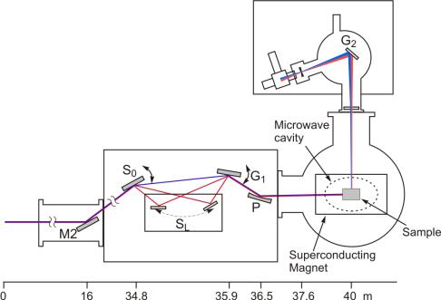
Fig.6.2 Soft X-ray spectroscopy experimental station-EH1
Soft X-ray Microscopy
The beamlines cryo-STXM (200-1000eV) and room temperature STXM (200-600eV) have similar optical scheme. The optical configuration of both beamlines is well matched to the optical configuration of high energy resolution grating monochromators. Radiation damage to the specimen is minimized because the Fresnel zone plate (with 10-20% efficiency) is positioned before the specimen. Scanning microscopes can image both large (millimeter) and small (micrometer) samples including the signals from luminescence.
The beam is spitted first using the water-cooled plane scraping M1, which intercepts about 65% of the central cone. This Ni-coated mirror deflects the beam by 80 mrad (4.6o) horizontally in the outboard direction (Fig. 6.1). Using second scraping mirror M3, the beam is split into two beams: for experimental hutch EH-2.1 (cryo-STXM, 50%) and experimental hutch EH-2.2 (STXM, 50%). The mirror M3 is the toroid that focuses the beam to input slit of EH-2.2 (Fig. 6.1). The undeflected part of the beam intercepts a second similar toroid M4 that plays the same focusing role for the inboard branch. Both toroids are made from single-crystal silicon blanks and are gold-coated over the footprint of the beam.
The spherical gratings monochromators (SGM) are mounted at the experimental hutches EH2.1 and EH2.2 for horizontally dispersing the photon beam (Fig.6.3). For high resolution focusing, the Fresnel zone plates equip the experimental hutches EH2.1 and EH2.2 that provide the finest zone width as small as 30 nm, and diameters as large as 160 mm.
Fig. 6.3 Scheme of X-ray microscopy experimental stations EH-2.1 and EH-2.2
Experimental stations
Spectroscopy (EH-1). The offered methods of investigation of luminescence excitation within 50-1800eV using soft X-spectroscopy are convenient for studying the energy and space structures in solids. Based on the luminescence investigations of these single-crystals at the fundamental absorption range it is possible to determine energy relaxation processes, photoabsorpsion and photoeffect mechanisms on inner atom shells. This will allow not only to understand known physical and chemical processes but also to predict other peculiarities of substances. The method of electro-paramagnetic resonance (EPR) was successfully used for studies of self-trapped holes, impurity atoms and defects in many classes of solids. In case of EPR studies of excited electronic states of atoms or defects the technique of optically detected magnetic resonance (ODMR) is widely used in which the excited state EPR is detected optically.
The investigations of the luminescence and radiation stimulation processes, which have sub-nanosecond times in solid states, for example – cross-luminescence, will be carried out on the second monochromator Seya-Namioka. The crystals are mounted on the supporters of the sample in the cryostat (4K<T<400K). Calibration of the monochromators will be done according to the emission spectra with well-known wavelengths, for example Hg. Standard photomultipliers, which are working in a regime of one photon registration, will be used as luminescence detectors.
In a measuring chamber, where the cryostat with a sample is mounted, the superconducting magnet (10T) microwave system (100-1000Hz) will be also mounted, to measure the EPR signals. Such station could be used for both time-resolved luminescence and EPR/ODMR study. Table 6.2 presents the main specifications of the spectroscopy experimental station EH-1.
Table 6.2 The specifications of the spectroscopy experimental station EH-1
| End station | Spectroscopy |
| Energy range | 50-1800 eV |
| Monochromators | Plane grating, 1200 1/mm,Seya-Namioka, 600, 1200, 2044 1/mm |
| Detectors | Photomultipliers; semiconductor diodes |
| Sample environment | Vacuum 10-6 Torr |
| Experimental techniques | Photoelectrons, transmission, reflectivity, EPR/ ODMR |
Microscopy (EH 2.1, EH2.2). The cryo-scanning transmission microscope (cryo-STXM-EH2.1) and scanning transmission X-ray microscope (STXM-EH2.2) use a Fresnel zone-plate lens to produce a demagnified image of the diffraction-limited undulator radiation mirror filtered through a pinhole (Fig. 6.3).
The Inboard branch (EH-2.1) has a cryo- scanning transmission microscope used to image and obtain oxygen and carbon XANES on biological samples. There is also a section where a room temperature STXM holography or diffraction chambers can be operated.
The Outboard branch (EH2.2) has a room temperature, and STXM can be performed in atmosphere to image and acquire Carbon and Oxygen XANES on less radiation sensitive samples, such as polymers, coal, bone and diamond.
Table 6.3 The specification of microscopy experimental stations EH-2.1 and EH-2.2.
| End station | Scanning transmission X-ray microscope (STXM) |
| Energy range | (200-1000 eV) cryo-STXM; (200-600 eV)- STXM; |
| Monochromator | SGM (gratings: 150, 392, 925 lines/mm) |
| Spatial resolution | < 100 nm |
| Detectors | Multi-channel silicon detector |
| Spot size at sample | 100 nm |
| Sample Format | Thin sections or thin films(100 nm thick), 3×3 nm area |
| Sample environment | Helium at 1 atm |
| Experimental techniques | Imaging, NEXAFS in small spots, local EXAFS |
Zone plates currently in use produce a spot size of 150 nm with a working distance between the order sorting aperture and the sample of 0,8 mm. An X-ray scanning stage moves the lens transversely through the X-ray illumination so that the focused spot is rastered across the sample surface. The instrument operates over the photon energy range from 200 to 1000 eV at selected values depending on the particular zone plate installed. Table 6.3 present the specifications for the experimental stations EH-2.1 and EH-2.2.
7 White Beam Diffraction
Many properties of materials can only be understood in terms of their microscopic structure. This analysis is routinely performed using a large variety of well-established X-ray techniques, such as spectroscopy, diffraction and imaging. The performance of CANDLE synchrotron radiation facility allows the experimental research that include:
- X-ray fluorescence study including trace element analysis;
- White beam X-ray topography;
- The study of material properties under the high pressure and high temperature;
- High resolution X-ray inelastic scattering (energy resolution ~2eV) investigations;
- Small angle X-ray scattering in noncrystalline materials;
- Mammography (experimental investigations) and phase contrast topography;
- High resolution X-ray diffraction and X-ray interferometry research;
- Microdiffraction analysis;
- R & D of the new X-ray optics elements.
The dipole synchrotron radiation beam with a moderate flux, “white” or tunable monochromatic radiation, will serve these experiments in material science.
X-ray fluorescence analysis bases on atomic inner shell processes. Once an atom has lost a core level electron by the absorption of a X-ray photon the hole is refilled by an electron from a higher shell. The released energy can either cause a third electron to leave the atom (Auger effect) or may be emitted as a high energy X-ray photon (fluorescence). The energy of a fluorescence photon is characteristic for the atom and every element contained in the sample leaves its characteristic fingerprint of X-ray fluorescence photons.
Two principle ways for the determination of the characteristic photons are possible: wavelength (WDX) and energy dispersive (EDX) systems. The former ones mainly consist of an analyzer crystal and a flow counter. EDX uses the semiconducter crystal to transform the incoming energy of a single photon into a well-defined number of electron hole pairs, representing a characteristic amount of charge for every incoming photon. A spectroscopic amplifier and a multi channel analyser (MCA) convert the charge signal to a numerical pointer and the photon is counted as an event of the appropriate energy in the computer. The complete spectra may be analyzed simultaneously, but the price is a lower resolution compared to WDX systems.
The detection of elements with atomic numbers between 20 and 92 is routinely possible with minimum detection limits (CMDL) of down to 0.1 pg/µg using the K lines as analytical signal. The sample support is mounted on a XYZ-table with reproducible positioning of about 0.5 mm. The fluorescence signal is recorded with an HPGe energy dispersive detector.
X-ray interferometry technique is incorporated into computed tomography (CT). By taking several interferometry images at different rotational orientations of a sample, is able to reconstruct a three-dimensional map of the refractive index inside the sample. With this technique, have studied a rat cerebellum and rabbit cancer lesions as well as cancerous tissues of human breast, liver, and kidney using synchrotron radiation. These results illustrate the potential advantages of phase contrast and its sensitivity to minute density variations – on the order of 10-9g/cm3. The researchers have recently shown that their phase-contrast CT results are similar to the images obtained with low-magnification (20%) optical microscopy, but without the need to generate contrast through staining. Because of its extreme sensitivity, the X-ray interferometer requires almost perfect crystal alignment and stability – on the order of 10-2 nm. The best results are obtained from a monolithic device in which all three X-ray mirrors are made from a single large crystalline silicon ingot. Although this technique provides inherent alignment and good stability, ingot sizes limit the potential field of view to about 3×3 cm2.
The phase-sensitive imaging is needed in perfect crystals study. As very sensitive angular filters that produce diffractometric images, it provides detailed images of the gradient of the refractive index in a sample. Synchrotron radiation that emerges from a monochromator is essentially parallel. As the X- rays traverse a sample placed between the monochromator and the angular filter (analyzer), they can be absorbed, scattered coherently or incoherently (by milliradians), or refracted through very small angles (microradians) due to the tiny variations in the refractive index. X-rays emerging from the sample and hitting the analyzer crystal will satisfy the conditions for Bragg diffraction only for a very narrow window of incident angles, typically on the order of a few mrad. X-rays that have been scattered in the sample will fall outside this window and won’t be reflected at all. Refracted X-rays within the window will be reflected, but the reflectivity depends on the incident angle. If the analyzer is perfectly aligned with the monochromator, it will filter out any X-rays that are scattered or refracted by more than a few mrad. The resulting image at the X-ray detector will resemble a standard X-ray radiograph but with enhanced contrast due to the scatter rejection. If, instead, the analyzer is oriented at a small angle with respect to the monochromator then X-rays refracted by a smaller angle will be reflected less, and X- rays refracted by a larger angle will be reflected more. Contrast is therefore established by the small differences in refracted angle of X-rays leaving the sample.
High resolution X-ray inelastic scattering (XIS) experiments with photon energies in the range 7-25 keV, for phonon and electronic excitations, with total resolution (monochromator and analyzer) of 7 meV and up to ~2 eV energy transfer, can be performed at primary photon-energy above the Si 777 back-reflection energy. Extensions up to the Si 999 reflection, providing resolution down to 5 meV, are also possible. The high-resolution XIS set-up aims to provide total energy-resolution in the range 0.1 – 1 eV, with energy transfers suitable to the exploitation of inelastic scattering from electron valence excitations, Raman and resonant Raman scattering in the photon energy range 7- 25 keV.
From above list of the application research to be conducted on this beamline, it is clear that this station has the multi-purpose meaning and therefore demands some flexibility in formation of beams with various degree of monochromatization and collimation, both on the optic hatch and workstation. The optical layout of beamlines is given on Fig. 7.1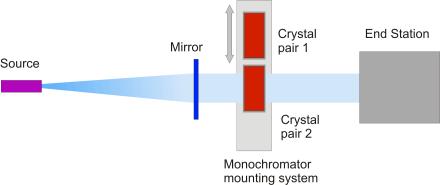
Fig. 7.1 The principal optic sketch of beamline
Radiation from a dipole with horizontal fun of 5 mrad is reflected from vertically collimating water-cooled mirror M. Mirror M will provide vertical collimation and remove monochromator diffraction higher order harmonics. The mirror consists from 1m long Si blank, Rh-coated (K-edge: 23 keV), which can be tilted up to θ =5 mrad and bent (5 < R < 30 km) as required for the desired photon energy. Further, the beam is reflected from DCM (Si 111 or 311, multilayered structure Si/W) with the fixed exit. If necessary, the second crystal of DCM may be sagittally bended for focusing in horizontal plane. With such arrangement of optical elements, the beam will be deviated from the initial direction on a double angle θ. The angle is conditioned by the working photon energy range to suppress harmonics.
Changing of planes of reflection 111 and 311 from silicon, or using multilayered structure Si /W allow to expand both the working wavelength area (from 5 up to 50keV) and the spectral resolution limits (DE/E~10-1~10-5 ) on the sample.
The Experimental apparatus in End Station of the beamline include:
-
High precision multipurpose 6-axis diffractometer SSY-1;
-
Varios Stuges (x/y/z/ q /Tilt);
-
“Amtek” thermoelectucally cooled “Rover” portable X-ray and g-ray spectroscopy
system;
-
In home designed precise q stages, monochromators, X-ray optical elements and
crystal benders;
-
NaI detector, ion chambers;
-
Goniometric heads;
-
Kirkpatrick-Baez mirror system.